Turboshaft: Difference between revisions
Adamcolton (talk | contribs) No edit summary |
Adamcolton (talk | contribs) No edit summary |
||
| (One intermediate revision by the same user not shown) | |||
| Line 15: | Line 15: | ||
If I do a simple metal compressor (which is probable for at least the first build), most builds do a lot of the work by hand. I think it would actually be easier, and definitely more accurate to build a jig. This would make a precision cut, then bend the blade, and possible add some curvature. | If I do a simple metal compressor (which is probable for at least the first build), most builds do a lot of the work by hand. I think it would actually be easier, and definitely more accurate to build a jig. This would make a precision cut, then bend the blade, and possible add some curvature. | ||
It's not a turboshaft, but it's a great breakdown of a compress. [https://www.youtube.com/watch?v=CXSi4GXUojo This video] shows some important details. The blades are curved so both ends are about 30° but the front end is closer to the plane of rotation and the back end is closer to the plane of flow (with centrifugal force, that will compress the air). The stators do the same thing in reverse. Front end is in line with the flow, the back is in line with rotation. | It's not a turboshaft, but it's a great breakdown of a compress. [https://www.youtube.com/watch?v=CXSi4GXUojo This video] shows some important details. The blades are curved so both ends are about 30° but the front end is closer to the plane of rotation and the back end is closer to the plane of flow (with centrifugal force, that will compress the air). The stators do the same thing in reverse. Front end is in line with the flow, the back is in line with rotation. Also note the the stator directs flow into the rotor blades. | ||
== For Robots == | |||
A small turbo shaft could provide electrical power. But it also provides energy that doesn't need to be transformed. An electrical control system could deliver the energy as needed. However, I need to look at transmission efficiencies. Hydraulic or pneumatic should be highly efficient, but the parts for these systems are pricey. I'd like to look at some diy pneumatic, but, again, efficiency. | |||
Latest revision as of 21:15, 30 December 2015
Half-baked.
A tin can turbo shaft. I've seen some tin can jet builds. I'd like to do that with a turboshaft. I like the designs where the compressed air is used to cool the combustion chamber, which also pre-heats the air.
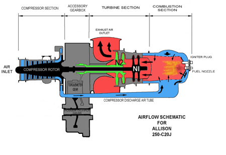
Output to a belt system. One component would be a motor/alternator. This could be used as the starter motor, but once the system was self-sustaining, it could be used as an alternator. This gives us an electrical source to run a fuel pump.
One idea I'd like to look at a bit more is using thermal expansion to my advantage. The seals around the hot components could be made of different metals with different thermal expansion so that they seal tighter at higher temperatures.
Looking at compressor designs, the vanes spiral and twist. I can simulate that with a few turbines. The ones closes to the front will be close to parallel with the plane of rotation, only a slight angle to get the air flowing back. The blades furthest back will be almost parallel to the shaft, they will compress the air with centrifugal force.
If I can successfully build one of these, there's a few places it could be useful. As either a large motor for a shop, or a small motor for hand tools (though that would need a hell of a heat exchange, probably water cooled - but maybe that could power a second turbine). A really small one would be awesome for a drone - but you'd have to control lift with angle of attack rather than blade speed. Finally, but probably most simple, a turboshaft go-kart would be crazy awesome.
It may work to make the compressor from plaster of paris. It's got a pretty high heat tolerance. Of course it won't stand up to much stress, but if things run smoothly, that shouldn't be much of an issue. The compressor can be built out of materials that are heat sensitive - things like carbon fiber or fiberglass.
If I do a simple metal compressor (which is probable for at least the first build), most builds do a lot of the work by hand. I think it would actually be easier, and definitely more accurate to build a jig. This would make a precision cut, then bend the blade, and possible add some curvature.
It's not a turboshaft, but it's a great breakdown of a compress. This video shows some important details. The blades are curved so both ends are about 30° but the front end is closer to the plane of rotation and the back end is closer to the plane of flow (with centrifugal force, that will compress the air). The stators do the same thing in reverse. Front end is in line with the flow, the back is in line with rotation. Also note the the stator directs flow into the rotor blades.
For Robots
A small turbo shaft could provide electrical power. But it also provides energy that doesn't need to be transformed. An electrical control system could deliver the energy as needed. However, I need to look at transmission efficiencies. Hydraulic or pneumatic should be highly efficient, but the parts for these systems are pricey. I'd like to look at some diy pneumatic, but, again, efficiency.