Breadboard: Difference between revisions
Adamcolton (talk | contribs) |
Adamcolton (talk | contribs) |
||
| Line 71: | Line 71: | ||
* V I probe | * V I probe | ||
* Zener diode ( current limit R → zener in parallel with pot and voltage meter) | * Zener diode ( current limit R → zener in parallel with pot and voltage meter) | ||
Simpler would be to just give every module a bank of general IO pins. Each module would have a sort of trapezoid footprint; 5 pins top left, 10 pins middle right, 5 pins bottom left. | |||
=== Storage === | === Storage === | ||
Revision as of 16:48, 5 January 2021
Good Resources
- https://runtimemicro.com/Construction/Permanent-Solderless-Breadboard-Projects
- https://youtu.be/Y3Kx2RlLXsY?t=980
Todo
- from this pre-cut resistors (330 & 10k) to jump power
- red and black jumpers for power
- LEDs with integrated 330 resistor and low side marking
- 16x2 HD44780 to Arduino Uno connector
- Arduino nano to Uno pinout
Advanced Breadboard
Slightly angled platform with space for 3 standard breadboards. Breadboards have tabs in the side to link them, we'll use that to hold them in place. That also means they can be swapped out, so I'll get ~6 of them. The board will have one global ground bus and 3 Vcc bus, each with it's own power switch, fuse, adjustment and voltage display. The board will have one standard barrel connector. There will be ground and Vcc terminals for each breadboard rail, though they will be shared by adjacent boards.
For peripherals, LEDs, buttons, switches, pots. The peripherals will have 2 terminal groups, between the bread boards. The LEDs will be in two banks - high and low. I'll put a linear regulator in current limiting mode for each of them (probably an LM723).
A breadboard is only 60 terminals long, so it would almost make sense to just use a breadboard to wire this up.
I can put a storage spot in the side for jumper wires.
I'd like the structure to fold up, the peripherals on the "wings", leaving enough space inside for parts. But I don't know how thick it would be and I'm not sure how the wiring would work with the hinges.
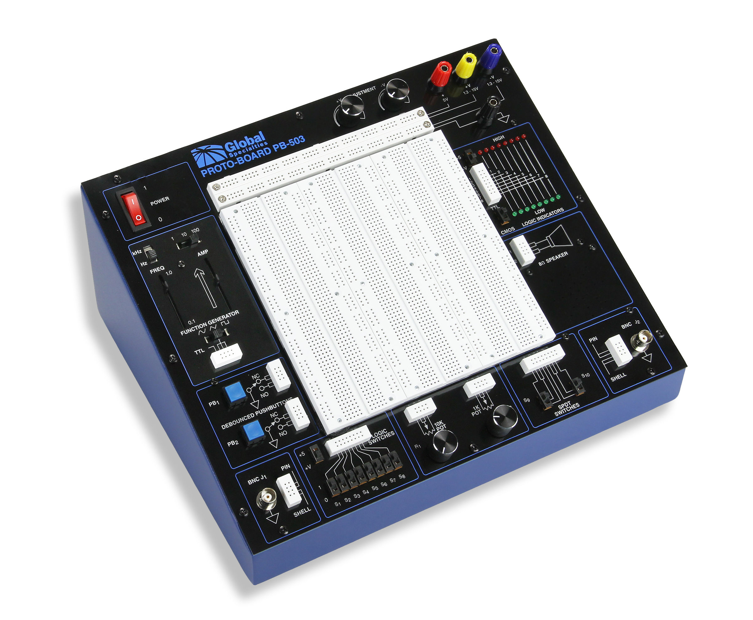
I saw this (look for "circuit design trainer") and I'd like to build one. It will be designed to hold 3 boards, but they will be held in place with their tabs, so I can swap out boards. I'll buy 6 to make sure I've got a good set.
Power
I like the idea of 3 sources, but I really almost never use more than one. And if there is only one, that simplifies a lot. So yeah, one adjustable power supply. Power in will come from a barrel jack. I will have one display for the current Voltage and Current. I could use another for the voltage in.
I need to choose a set input power limit. Probably 24V. This lets me feed the Arduino's ADC with a simple voltage divider. It would be nice to add over voltage protection.
Current Limit
I really want two things here, one is a current limit and the other is a circuit breaker. The input to both will come from the Arduino, but the circuit needs to work on it's own to be fast.
I will use an op amp for the current limit. The input will come from a PWM on the Arduino. Op amp feeds a mosfet. https://www.youtube.com/watch?v=tIrfChM1f7Q
I can have the max current limit relatively low because it's intended to protect sensitive control circuits. If I'm trying to drive power components they can can access the power line directly.
Arduino
I think I want one LCD display connected to an Arduino. Most of the time it will display the power settings - Vcc, current and computed power. But it will also let me show the voltage at the plug.
I can also provide some more advanced tools. PWM, maybe a frequency counter. Some basic multimeter style probes to the circuit.
I think the input can be just a rotary encoder. Output could be either and LCD or an OLED. Former is easier, latter gives me more options.
Arduino Nano has 14 IO (6PWM 6ADC)
- Current limit (PWM)
- Current Cutoff (PWM)
- Voltage limit (PWM)
- Rotary encoder (3 digital)
- Power Voltage (ADC)
- Vcc (ADC)
- Current (ADC)
- Display (???)
Sockets
Rather than the built in peripherals, I may be able to design a socket system. I think the small perf boards I have would be the perfect size. Modules would plug in, they would connect to Power, Vcc and Gnd. Power is the plug level input allowing the module to access higher power where necessary. I could also provide I2C or SPI back to the Arduino.
Socket Pins
- Plug V+
- Regulator V+
- Gnd
- General IO
Modules
- LED bank
- Pots w/ voltage meter
- Buttons
- Switches
- LCD
- Astable 555
- Negative Feedback Op Amp
- V I probe
- Zener diode ( current limit R → zener in parallel with pot and voltage meter)
Simpler would be to just give every module a bank of general IO pins. Each module would have a sort of trapezoid footprint; 5 pins top left, 10 pins middle right, 5 pins bottom left.
Storage
I want enough storage built in so that I can store the breadboards not in use, all the socket modules and the wires. And tweesers.
V1
This all sounds great, but it's a lot of work. I should bootstrap with a simpler version.
Layout/Storage
Since this should be simple, I will prototype this. So 3 boards, sockets, voltage breakout. Everything. Also storage for parts.
Power
Fairly simple - DC jack for input fed into a buck converter. I'll use a standalone voltage module. I can rewire the pot to a nice one on the board. I'll add one of the pico fuses for protection.